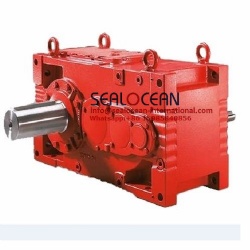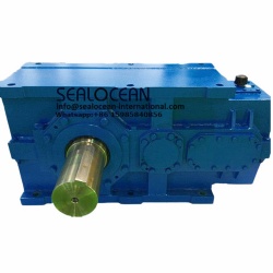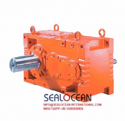


Product name : CHINA FACTORY H SERIES RIGHT ANGLE PUMP DRIVE . USED FOR THE TRANSMISSION AND VARIABLE SPEED OF DEEP WELL PUMPS, AXIAL FLOW PUMPS, OBLIQUE FLOW PUMPS, LONG SHAFT PUMPS, SUBMERSIBLE PUMPS , VERTICAL SHAFT WORKING MACHINES.
Product No. : 202241694939
Details:
Features and Application
H Series Right Angle Pump Drive can transmit the prime mover horizontal axis power to the vertical pump axis, which is economical, efficient, space-saving and suitable for various climatic conditions.
H Series Right Angle Pump Drive is directly matched with diesel engine, horizontal motor or steam turbine, which can be used for transmission and speed change of various vertical pumps such as long-axis pump, deep well pump, diagonal flow pump, axial flow pump and submerged pump as well as the right angle transmission and speed change of various vertical axis machines. The H-series right angle gearbox can directly support the axial forces that may exist in the machine and simplify the structure of the machine. Can be widely used in farmland irrigation, water conservancy engineering, municipal engineering, metallurgical mine, petrochemical engineering, fire control and marine engineering, etc.
A variety of models and transmission ratios can meet the requirements of high and low speed prime movers and pumps.
Speed Grading
Table 1
|
Vertical axis speed
(r/min)
|
Horizontal axis speed (r/min)
|
|||||||
|
Speed increase ratio ——Active: slave
|
||||||||
|
1:2
|
4:7
|
2:3
|
3:4
|
4:5
|
5:6
|
10:11
|
1:1
|
|
|
490
|
245
|
280
|
327
|
368
|
392
|
408
|
445
|
490
|
|
580
|
290
|
331
|
387
|
435
|
464
|
483
|
527
|
580
|
|
690
|
345
|
394
|
460
|
518
|
552
|
575
|
627
|
690
|
|
720
|
360
|
411
|
480
|
540
|
576
|
600
|
655
|
720
|
|
860
|
430
|
491
|
573
|
645
|
688
|
717
|
782
|
860
|
|
960
|
480
|
549
|
640
|
720
|
768
|
800
|
873
|
960
|
|
1160
|
580
|
663
|
773
|
870
|
928
|
967
|
1055
|
1160
|
|
1460
|
730
|
843
|
973
|
1095
|
1168
|
1217
|
1327
|
1460
|
|
1760
|
880
|
1006
|
1173
|
1320
|
1408
|
1467
|
1600
|
1760
|
|
3460*
|
1730
|
1977
|
2307
|
2595
|
2768
|
2883
|
3145
|
3460
|
|
Vertical axis speed
(r/min)
|
Horizontal axis speed (r/min)
|
||||||||||
|
Speed decrease ratio -- Active: slave
|
|||||||||||
|
11:10
|
6:5
|
5:4
|
4:3
|
3:2
|
7:4
|
2:1
|
9:4
|
5:2
|
3:1
|
4:1
|
|
|
490
|
539
|
588
|
613
|
653
|
735
|
858
|
980
|
1103
|
1225
|
1470
|
1960
|
|
580
|
638
|
696
|
725
|
733
|
870
|
1015
|
1160
|
1305
|
1450
|
1740
|
2320
|
|
690
|
759
|
828
|
863
|
920
|
1035
|
1208
|
1380
|
1553
|
1725
|
2070
|
—
|
|
720
|
792
|
864
|
900
|
960
|
1080
|
1260
|
1440
|
1620
|
1800
|
2160
|
—
|
|
860
|
946
|
1032
|
1075
|
1147
|
1290
|
1505
|
1720
|
1935
|
2150
|
2580
|
—
|
|
960
|
1056
|
1152
|
1200
|
1280
|
1440
|
1680
|
1920
|
2160
|
2400
|
2880
|
—
|
|
1160
|
1276
|
1392
|
1450
|
1547
|
1740
|
2030
|
2320
|
2610
|
2900
|
3480
|
—
|
|
1460
|
1606
|
1752
|
1825
|
1947
|
2190
|
2555
|
2920
|
3285
|
3650
|
—
|
—
|
|
1760
|
1936
|
2112
|
2200
|
2347
|
2640
|
3080
|
3520
|
—
|
—
|
—
|
—
|
* Please consult our company
Selection of Parameter
When it is used to drive deep well pumps, the parameters in Table 2 already contain suitable load factors, which can be directly selected by the user. For other situations, please consult our company.
The American Gear Manufacturing Association stipulates that the spiral bevel gear load factor shall be greater than or equal to 1.5, and the load factor values shall be different for different applications. In addition, other factors affecting the rated power of the gearbox include bearing, axis, temperature and lubrication, which have been taken into account in Table 2.
The selection of oil cooling method should take factors such as thrust, speed, ventilation environment and operating conditions into account. For a gearbox equipped with an oil cooler, it shall be operated with a coolant of about 20 ℃.
Selection of Thrust Bearing Form
The upper part of the vertical axis (hollow axis) is made of bearings that can withstand large thrusts, which can meet the requirements of most pumps and different heads. In most cases, the thrust of the gearbox itself is mainly used to reduce the load that the pump acts on the "thrust bearing" of the vertical axis, so there is a minimum downward thrust to prevent the vertical axis "thrust bearing" from separating.
Unless otherwise noted, H-series gearbox is generally arranged in the DT format shown in the figure, corresponding to the "standard" thrust shown in Table 2.
If there is insufficient "upward thrust" or "downward thrust", it can be arranged in the DF format shown in the figure, corresponding to the "two-way" thrust shown in Table 2.
If the "downward thrust" exceeds the standard thrust value shown in Table 2, it can be selected by heavy type, corresponding to the DT/DT arrangement format shown in the figure.
The heavy type can also be arranged according to the DF/DT format shown in the figure. At this time, the downward thrust corresponds to the "standard, thrust value" in Table 2, and the upward thrust is selected according to "two-way" in Table 2.
Table 2 Thrust value
|
Model
|
Vertical axis speed (r/min)
|
Power
HP/kW
|
Standard
|
Heavy type
|
Two-way
|
||
|
Single downward thrust (N)
|
Maximum downward or upward thrust(N)
|
||||||
|
Minimum
|
Maximum
|
Minimum
|
Maximum
|
||||
|
H80
|
860
960
1160
1460
1760
|
46/34
50/37
58/43
69/51
80/60
|
9120
8980
8680
8000
7560
|
32900
31540
30700
28500
26700
|
6675
|
43200
42100
40500
36900
35600
|
19600
19100
18250
16910
13350
|
|
H110
|
860
960
1160
1460
1760
|
63/46
69/51
80/60
95/70
110/81
|
10450
9920
9790
9120
8450
|
32900
31540
30700
28500
26700
|
8000
|
43200
42100
40500
37800
35600
|
19600
19100
18250
16910
13350
|
|
H125
|
720
|
63/46
|
12900
|
37800
|
12460
|
54300
|
22700
|
|
860
|
72/53
|
12000
|
35600
|
11800
|
51600
|
21400
|
|
|
960
|
79/58
|
11780
|
34790
|
11560
|
50400
|
21000
|
|
|
1160
|
90/66
|
11350
|
33400
|
11100
|
48000
|
20000
|
|
|
1460
|
108/79
|
10680
|
31150
|
10200
|
44900
|
18700
|
|
|
1760
|
125/92
|
9790
|
28900
|
9800
|
42300
|
17400
|
|
|
Model
|
Vertical axis speed
(r/min)
|
Power HP/kW
|
Standard
|
Heavy type
|
Two-way
|
||
|
Single downward thrust (N)
|
Maximum downward or upward thrust
|
||||||
|
Minimum
|
Maximum
|
Minimum
|
Maximum
|
(N)
|
|||
|
H150
|
720
|
75/55
|
13570
|
43600
|
14000
|
66750
|
26250
|
|
860
|
87/64
|
13130
|
41830
|
13350
|
63630
|
24900
|
|
|
960
|
95/70
|
12890
|
40120
|
13000
|
62120
|
24100
|
|
|
1160
|
108/79
|
12240
|
39160
|
12460
|
59180
|
23600
|
|
|
1460
|
129/95
|
11570
|
36930
|
11570
|
55620
|
22250
|
|
|
1760
|
150/110
|
11120
|
35600
|
11120
|
53400
|
21360
|
|
|
H200
|
720
|
100/73.5
|
16000
|
53400
|
15130
|
72085
|
30000
|
|
860
|
116/85
|
14680
|
48950
|
14240
|
68080
|
28000
|
|
|
960
|
126/93
|
14100
|
47680
|
13920
|
65610
|
27000
|
|
|
1160
|
144/106
|
13570
|
45400
|
13350
|
63630
|
25360
|
|
|
1460
|
172/126.5
|
12680
|
42270
|
12680
|
60000
|
23580
|
|
|
1760
|
200/147
|
12000
|
40000
|
12000
|
57850
|
22690
|
|
|
H300
|
720
|
150/110
|
16700
|
60700
|
16700
|
83660
|
36500
|
|
860
|
174/128
|
15800
|
57850
|
16000
|
79650
|
34700
|
|
|
960
|
189/139
|
15500
|
56100
|
15600
|
77210
|
33200
|
|
|
1160
|
216/159
|
14900
|
54300
|
14900
|
74310
|
32500
|
|
|
1460
|
258/190
|
14000
|
51200
|
14000
|
69860
|
30700
|
|
|
1760
|
300/220
|
13350
|
48950
|
13350
|
66750
|
29400
|
|
|
H350
|
720
|
175/129
|
18900
|
72530
|
18700
|
89000
|
43600
|
|
860
|
203/149
|
18000
|
68970
|
17800
|
84500
|
41400
|
|
|
960
|
221/162
|
17700
|
67300
|
17400
|
82400
|
40300
|
|
|
1160
|
252/185
|
16700
|
64100
|
16700
|
79200
|
38300
|
|
|
1460
|
301/221
|
15800
|
60500
|
15600
|
74300
|
36500
|
|
|
1760
|
350/257
|
15130
|
57850
|
15100
|
71200
|
34700
|
|
|
H425
|
720
|
213/156.5
|
20700
|
83200
|
21100
|
111200
|
49840
|
|
860
|
246/181
|
19800
|
79650
|
20200
|
106800
|
47610
|
|
|
960
|
268/197
|
19100
|
77230
|
19700
|
103700
|
46510
|
|
|
1160
|
306/225
|
18500
|
73870
|
18700
|
97900
|
44500
|
|
|
1460
|
366/269
|
17350
|
69860
|
17800
|
93400
|
41830
|
|
|
1760
|
425/312
|
16900
|
66750
|
16900
|
89000
|
40050
|
|
|
H500
|
720
|
250/184
|
23360
|
83200
|
23360
|
111200
|
49840
|
|
860
|
290/213
|
22250
|
79650
|
22470
|
106800
|
47610
|
|
|
960
|
315/232
|
21870
|
77160
|
21670
|
103700
|
46510
|
|
|
1160
|
360/265
|
20700
|
73870
|
20470
|
97900
|
44500
|
|
|
1460
|
430/316
|
19580
|
69860
|
19580
|
93400
|
41830
|
|
|
1760
|
500/367.5
|
18690
|
66750
|
18690
|
89000
|
40050
|
|
|
H600
|
720
|
300/220
|
24500
|
89000
|
24250
|
115700
|
53400
|
|
860
|
348/256
|
23140
|
84500
|
23360
|
111200
|
50730
|
|
|
960
|
378/278
|
22670
|
82400
|
22770
|
107100
|
49720
|
|
|
1160
|
432/317
|
21800
|
79200
|
21580
|
102300
|
47610
|
|
|
1460
|
516/379
|
20500
|
74300
|
20470
|
97900
|
44500
|
|
|
1760
|
600/441
|
19580
|
71200
|
19580
|
93400
|
42720
|
|
|
H750
|
720
|
375/276
|
27600
|
89000
|
27800
|
115700
|
53400
|
|
860
|
435/320
|
26250
|
84500
|
26700
|
111200
|
50730
|
|
|
960
|
473/347
|
25300
|
82800
|
26000
|
107100
|
49720
|
|
|
1160
|
540/397
|
24500
|
79200
|
24500
|
102300
|
47610
|
|
|
1460
|
645/474
|
23140
|
74300
|
23580
|
97900
|
44500
|
|
|
1760
|
750/551
|
22250
|
71200
|
22250
|
93400
|
42720
|
|
|
H1000
|
490
|
279/205
|
34500
|
108000
|
37500
|
125000
|
60000
|
|
580
|
329/242
|
32000
|
102000
|
34200
|
120000
|
57800
|
|
|
720
|
408/300
|
30700
|
97000
|
30900
|
115700
|
53400
|
|
|
860
|
488/359
|
29340
|
93400
|
29700
|
111200
|
50730
|
|
|
960
|
544/400
|
28500
|
91700
|
29200
|
107100
|
49720
|
|
|
1160
|
660/485
|
27600
|
87300
|
28500
|
102300
|
47610
|
|
|
1460
|
830/610
|
26250
|
84500
|
27200
|
97900
|
44500
|
|
|
1760
|
1000/735
|
24000
|
79100
|
25000
|
93400
|
42720
|
|
|
H1360
|
490
|
680/500
|
35000
|
108000
|
38600
|
125000
|
60000
|
|
580
|
821/604
|
32600
|
102000
|
35400
|
120000
|
57800
|
|
|
720
|
1020/750
|
31200
|
97000
|
31800
|
115700
|
53400
|
|
|
860
|
1217/895
|
29800
|
93400
|
30600
|
111200
|
50730
|
|
|
960
|
1360/1000
|
29700
|
91700
|
30200
|
107100
|
49720
|
|
|
1160
|
1643/1208
|
28200
|
87300
|
29500
|
102300
|
47610
|
|
|
1460
|
2067/1520
|
26900
|
84500
|
28300
|
97900
|
44500
|
|
Table 2A Power and Bearing Thrust Values at Different Speeds
|
Vertical axis speed (r/min)
|
490
|
580
|
690
|
720
|
860
|
960
|
1160
|
1460
|
1760
|
2000
|
2200
|
2400*
|
2800*
|
3000*
|
|
% of power at 1760r/min
|
30
|
43
|
48
|
50
|
58
|
63
|
72
|
86
|
100
|
105
|
111
|
116
|
128
|
133
|
|
% of thrust at 1760r/min
|
150
|
144
|
136
|
134
|
126
|
122
|
115
|
106
|
100
|
96
|
92
|
90
|
85
|
83
|
Note: 1. Parameters in Table 2 are only for FIG. 1 indicates the direction of rotation, please consult our company for other directions of rotation;
2. If the vertical axis speed exceeds 2200r/min, please contact our company.
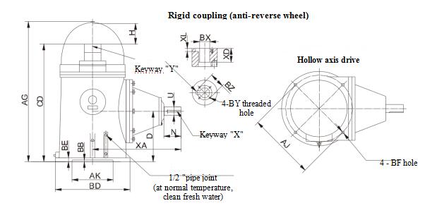
Dimensions (According to NEMA Standards)
Table 3 Dimensions (mm)
|
Model
|
CD
|
D
|
U
|
XA
|
N
|
AG
|
H
|
BE
|
BD
|
AJ
|
AK
|
BB
|
BF
|
Keyway "X"
|
Max.BX
|
XD
|
|
|
FIG.1,4
|
FIG.2,3
|
||||||||||||||||
|
H80
|
514
|
228.5
|
48
|
419
|
90
|
629
|
102
|
19
|
419
|
375
|
343
|
5
|
18
|
14X4.5X70
|
40
|
None
|
45
|
|
H110
|
635
|
289
|
50
|
445
|
90
|
749
|
102
|
25
|
419
|
375
|
343
|
5
|
18
|
14X4.5X70
|
50
|
50
|
54
|
|
H125
|
635
|
289
|
50
|
445
|
90
|
749
|
102
|
25
|
419
|
375
|
343
|
5
|
18
|
14X4.5X70
|
50
|
50
|
54
|
|
H150
|
762
|
336.5
|
60
|
521
|
120
|
876
|
102
|
25
|
508
|
375
|
343
|
5
|
18
|
18X5.5X95
|
55
|
55
|
60
|
|
H200
|
762
|
336.5
|
60
|
521
|
120
|
876
|
102
|
25
|
508
|
375
|
343
|
5
|
18
|
18X5.5X95
|
55
|
55
|
60
|
|
H300
|
870
|
381
|
70
|
610
|
140
|
1016
|
133
|
29
|
508
|
375
|
343
|
5
|
18
|
20X6X121
|
60
|
60
|
66
|
|
H350
|
978
|
419
|
70
|
737
|
140
|
1168
|
178
|
32
|
622
|
559*
|
343
|
10
|
24
|
20X6X121
|
60
|
60
|
76
|
|
H425
|
1003
|
419
|
75
|
762
|
145
|
1168
|
159
|
32
|
622
|
559*
|
343
|
10
|
24
|
20X6X121
|
60
|
60
|
85
|
|
H500
|
1003
|
419
|
90
|
787
|
170
|
1168
|
159
|
32
|
622
|
559*
|
343
|
10
|
24
|
25X7X140
|
75
|
75
|
85
|
|
H600
|
1080
|
419
|
95
|
838
|
190
|
1295
|
203
|
32
|
622
|
559*
|
343
|
10
|
24
|
25X7X140
|
75
|
80
|
100
|
|
H750
|
1162
|
482.5
|
100
|
914
|
190
|
1372
|
197
|
38
|
775
|
660
|
559
|
10
|
24
|
28X8X152
|
90
|
90
|
100
|
|
H1000
|
1405
|
545
|
110
|
1043
|
210
|
1610
|
153
|
35
|
920
|
860
|
600
|
7
|
8-28
|
28X8X170
|
100
|
||
|
H1360
|
1507
|
550
|
130
|
1290
|
250
|
1725
|
153
|
35
|
1250
|
1180
|
1120
|
-5
|
8-28
|
32X9X220
|
110
|
||
Note: ① Dimensions of CD and H may change when the heavy type thrust drive is used; Dimensions of XA, U, N and X may change when the speed decrease ratio is 7:4-4:1, please contact our company.
②Dimensions of D, CD, AG, XA, U, N and X may change when the speed increase ratio is 3:4-1:2, please contact our company.
③4 cases, namely the direction of rotation shown in FIG.2-FIG.4, heavy type thrust, speed decrease ratio of 7:4~3:1, and the speed increase ratio of 3:4-1:2, it is produced according to the special order.
④Tolerance: Axis diameter U, base groove AK, coupling hole BX
⑤* 4 pieces of M16 screw holes (depth: 25) can also be arranged on the circumference of a circle with the diameter of Φ375.
Transportation Weight and Size
|
Model
|
Net weight kg
|
Gross weight --Kg
|
Packing container dimension -- (mm)
|
Volume m3
|
||||
|
Domestic
|
Container
|
Plywood box
|
Length
|
Width
|
Height
|
|||
|
H80
|
130
|
140
|
145
|
155
|
635
|
485
|
940
|
0.29
|
|
H110
|
175
|
186
|
195
|
200
|
635
|
485
|
940
|
0.29
|
|
H125
|
180
|
190
|
198
|
205
|
635
|
485
|
940
|
0.29
|
|
H150
|
290
|
310
|
320
|
330
|
840
|
585
|
1120
|
0.55
|
|
H200
|
290
|
310
|
320
|
330
|
840
|
585
|
1120
|
0.55
|
|
H300
|
410
|
455
|
455
|
480
|
1020
|
765
|
1295
|
1.1
|
|
H350
|
630
|
680
|
680
|
705
|
1170
|
765
|
1320
|
1.2
|
|
H425
|
720
|
770
|
770
|
795
|
1170
|
765
|
1320
|
1.2
|
|
H500
|
730
|
780
|
780
|
805
|
1170
|
765
|
1320
|
1.2
|
|
H600
|
930
|
1010
|
——
|
1050
|
1270
|
790
|
1500
|
1.5
|
|
H750
|
1370
|
1480
|
——
|
1540
|
1450
|
965
|
1550
|
2.2
|
|
H1000
|
2200
|
2480
|
——
|
1560
|
2050
|
1100
|
1800
|
4.1
|
|
H1360
|
2800
|
3000
|
——
|
3080
|
2200
|
1450
|
1950
|
6.2
|
Note: Actual weight and size may vary slightly
Table 3A: Standard drive part connection dimension
|
Hole BX
|
Bolt circumference BZ
|
Thread BY
|
Depth XL
|
Keyway Y (width x depth)
|
|
φ25
|
φ46
|
4-M6
|
9
|
8x3.3
|
|
φ30
|
φ60
|
4-M8
|
9
|
8x3.3
|
|
φ35
|
φ60
|
4-M8
|
11
|
10 x 3.3
|
|
φ40
|
φ70
|
4-M8
|
13
|
12x 3.3
|
|
φ45
|
φ70
|
4-M8
|
15
|
14x3.8
|
|
φ50
|
φ80 (H125)
|
4-M10
|
15
|
14x3.8
|
|
φ50
|
φ90
|
4-M10
|
15
|
14x3.8
|
|
φ55
|
φ90
|
4-M10
|
17
|
16x4.3
|
|
φ60
|
φ100
|
4-M10
|
19
|
18x4.4
|
|
(φ65)
|
(φ100 )
|
4-M10
|
19
|
18x4.4
|
|
φ70
|
φ140
|
4-M10
|
21
|
20 x 4.9
|
|
(φ75)
|
(φ140 )
|
4-M10
|
21
|
20 x 4.9
|
|
φ80
|
φ140
|
4-M10
|
23
|
22 x 5.4
|
|
φ90
|
φ150
|
4-M10
|
26
|
25 x 5.4
|
|
φ100
|
φ160
|
4-M10
|
29
|
28 x 6.4
|
|
φ110
|
φ160
|
4-M12
|
29
|
28 x 6.4
|
Related Products: